170 Owner Performs Gender Change Operation - No Anesthetic!

A place to relax and discuss flying topics.

Moderators: GAHorn, Karl Towle, Bruce Fenstermacher

Post Reply
4-Shipp
Posts: 434
Joined: Mon Apr 22, 2002 11:31 pm

170 Owner Performs Gender Change Operation - No Anesthetic!

Post by 4-Shipp »

...a sex change on a barn, that is.

We are several weeks into a much talked about, much anticipated and much put off change from a barn to a hangar. All materials are on sight, the vertical posts and a 40', 640# header are in place and I am cutting and welding like nobody's business.

The biggest delay was the 2-3 weeks it took my to re-learn how to weld 8O

I visited George's hangar last spring and decided to replicate his single piece electric overhead type door*. I hope to have the hangar airplane ready by mid December.

I have been taking pictures and will post them soon. More to follow.

Bruce

* http://cessna170.org/phpBB2/viewtopic.php?p=42001#42001
Bruce Shipp
former owners of N49CP, '53 C170B
User avatar
N171TD
Posts: 103
Joined: Wed Aug 09, 2006 11:05 pm

Post by N171TD »

Shouldn't this be in the Hangar forum :lol:
Our 172/170 or a 171 is known as tweener
4-Shipp
Posts: 434
Joined: Mon Apr 22, 2002 11:31 pm

Update

Post by 4-Shipp »

The Header is welded in place. The remainder of the overhead structure is clamped in place but not welded. I went to open my new box of welding rod and realized I bout the wrong size so the welding will have to wait.

Most of today was spent double checking the measurements and geometry to ensure everything will clear when the door opens. There are enough differences between my building and George's building to keep me on my toes. My door will actually be recessed back into the barn about 6 inches. This allowed me to place the vertical supports behind the existing corner posts instead of inside them, thus making the door 8 inches wider. What I almost didn't catch was the fact that now the cable lift mechanisms that exit the front of the hangar stick out 6 inches less and clearance for the sheaves and door posts in the open position were minimal. I had to move things out about an inch but I don't think it will affect the balance of the door too much. Just a 1% change in the balance point so only about another 15-20 pounds on the chains and trolley tracks.

Tonight I mounted the boat lift to the bracket. I welded the bracket out of 2" angle iron and then welded that to the top of the header. Six bolts are used to mount the boat lift and of course the middle holes are offset slightly between the end holes. You guessed it, I welded the bracket to the header upside down so the center holes were biased the wrong way. It only took 30 minutes or so to drag the drill and tools up the scaffolding to re-drill the center holes. Not a big deal by itself but just one of a myriad of small challenges that are turning this into a true holiday project. It WILL be done by Christmas as I promised the FBO I would be out of their hangar by 1 January.

I am off on a trip tomorrow and hope to get some pics posted.

Bruce
Bruce Shipp
former owners of N49CP, '53 C170B
4-Shipp
Posts: 434
Joined: Mon Apr 22, 2002 11:31 pm

Pictures

Post by 4-Shipp »

Here are a few picks of the progress so far:


Image
This is the wall that will soon be a door

Image
There is a door in here somewhere!

Image
Vertical beams, header and 3x3 tubing to support he lift cables in place.

Image
Boat lift mounted to the header

Image
Sheaves exiting front of building for lifting cables

Image
Like a stray puppy..."please let me come inside..."

more to follow

Bruce
Bruce Shipp
former owners of N49CP, '53 C170B
4-Shipp
Posts: 434
Joined: Mon Apr 22, 2002 11:31 pm

Update

Post by 4-Shipp »

Well things are progressing but slower than anticipated. I finally finished the welding on the door itself about 4 pm today. Unfortunately I had hoped to have it done by 11 am! Everything is taking twice as long as I estimate it will. Actually, I must be making progress as last week things took three times as long as planned!

All that is left is take down the existing wall, transfer the sheeting to the door, run the cables, lift the door into place and attach the top of the door to the trollies. I should have 9CP at home and tucked in bed by Thursday sometime.

I'd post pictures but it is late and cold and they have not been taken yet, so they will have to wait. It is very exciting to see things finally come together. I'll post pictures of the rest of the progress after things are finished.
Bruce Shipp
former owners of N49CP, '53 C170B
4-Shipp
Posts: 434
Joined: Mon Apr 22, 2002 11:31 pm

Pictures!

Post by 4-Shipp »

Image

Finally got the frame welded. This took much longer than anticipated. Brush, weld, brush, grind...and on and on and on!

Image

Overhead door is gone

Image

The sheeting came down next.

Image

My buddy sprayed the field next door. Had to take a break and get some cool pics.

Image

Now the perlin.

Image

This was the scary part. Three structural vertical pipes had to be removed with a cutting torch. Took about an hour and the center of the header dropped less than 1/16" after everything was gone. No turning back now! :twisted:

Image

Air Tractor buddy came by and helped me sheet the doors. Hey, it got dark out!

Image

Installing the weather stripping. 8" wide sheets of 1/8" rubber doubled over and sandwiched between the sheeting and the froame. Very easy to do.

That took me to 1130 pm and I said uncle! Tomorrow I have to weld in some tabs to keep the cable on the sheaves, run the cable, lift the door into place and rig it for proper operation. I still need to get new flashing and trim but that will wait until after Christmas.

9CP should spend her first night here tomorrow! Yea!!!!

Bruce
Bruce Shipp
former owners of N49CP, '53 C170B
User avatar
GAHorn
Posts: 21291
Joined: Fri Apr 12, 2002 8:45 pm

Post by GAHorn »

Lookin' good, Bruce! Wonderin' how you're planning to lift the door into position.

Once it's in-place... You're going to suspend it at the ends by wheels? Or by pins. :?:

How 'bout a pic of how the overhead frames are attached to the inner rafter area, and your trolley-track set-up. :?:
'53 B-model N146YS SN:25713
50th Anniversary of Flight Model. Winner-Best Original 170B, 100th Anniversary of Flight Convention.
An originality nut (mostly) for the right reasons. ;)
User avatar
n3833v
Posts: 858
Joined: Tue Apr 23, 2002 6:02 pm

Post by n3833v »

I see a gas can close by, is that to start or put out the fire? :) The project looks good. Are you going to support the overhead that dropped? I always think how I could maybe do something upstate where I live. Well sometime.
Have a MERRY CHRISTMAS and a HAPPY NEW YEAR everyone.

John
John Hess
Past President 2018-2021
President 2016-2018, TIC170A
Vice President 2014-2016, TIC170A
Director 2005-2014, TIC170A
N3833V Flying for Fun
'67 XLH 900 Harley Sportster
EAA Chapter 390 Pres since 2006
K3KNT
4-Shipp
Posts: 434
Joined: Mon Apr 22, 2002 11:31 pm

Post by 4-Shipp »

George,

The door will be slid forward into position under the header. I purchased extra cable so I have enough to reach the door while it is on the ground. I will use the boat lift to raise the door to the mid-point and I can insert the door stops. These are appropriate lengths of 2x4 tubing with a plate welded on one end to support the wheel. I will have to support the top of the door and keep it level as the door is raised but my calculations show that will only be a 100-110 pound load so a rope over the rafters should do the trick. Once the vertical supports are in place, I will lower the door to its final upright position and install the trolleys and chains.

I used wheels for the side supports. I made them from 5" x7/8" steel sheaves. I cut a section of V-belt to length, filled the grove of the sheave with clear silicon, inserted the V-belt and "squozed" it all together with a length of bailing wire around the outside and twisted it as tight as I could.

I attached the the aft end of the overhead frames to the truss (these are constructed from 2 3/8" steel tubing) with 1/2" suspension u-bolts and a 3/16" plate. Worked slick and allowed a bit of movement to let the assembly find it's natural position prior to tightening with no weld induced stresses.

The trolley tracks are commercial units with mounting tabs pre-welded in place. They are rated to 400# per trolley and were screwed to the 3" square tubing as per mfg instructions. I opted to go with one trolly per side as there should only be 60# load per side. Even if one fails the other has a 3-1 safety factor.

John, I had just ran the welder out of gas. Yes, I need to make sure it is moved :oops:

Hey, what could possibly go wrong???

OK, coffee time is over and now it is time to get this finished. I'll get pics of the other details and post them tonight. Yee Ha!
Bruce Shipp
former owners of N49CP, '53 C170B
User avatar
170C
Posts: 3182
Joined: Tue May 06, 2003 11:59 am

Barn Sex Change

Post by 170C »

Boy Bruce, that project is coming along great from what the photos show. Thanks for sharing. I'm glad to know somebody else's projects, big or small, take 2-3 times longer than planned like mine do :P AND I am glad to see another good ole West Texas boy using "baleing wor" on his projects. I couldn't get by without it myself :wink: Hope you get the bird into the new hangar before the Saturday cold front comes through. That wind will give your project a good test. It sure would be fun to fly one of those Air Tractors, but maybe with a little bit more altitude than those guys do.

Have a Merry Christmas.
OLE POKEY
170C
Director:
2012-2018
User avatar
GAHorn
Posts: 21291
Joined: Fri Apr 12, 2002 8:45 pm

Post by GAHorn »

Bruce, it sounds like a good plan. I agree on the trolley capacity, as well. (As you know, I overbuilt mine a bit.)

It looks like you're doing good work! I like your adaptations a lot!

John, .... his overhead is replaced by the Flange-beam already in place which will support the door-lift as well.

Image
By-the-way, ... that looks like about a 14" beam... is that right, Bruce? (Oughta be plenty-strong! Mine is a 10" beam for a much heavier door. Compare it to the rafter above it, which is 14".)
Image
'53 B-model N146YS SN:25713
50th Anniversary of Flight Model. Winner-Best Original 170B, 100th Anniversary of Flight Convention.
An originality nut (mostly) for the right reasons. ;)
4-Shipp
Posts: 434
Joined: Mon Apr 22, 2002 11:31 pm

Done!!!!!!!!!

Post by 4-Shipp »

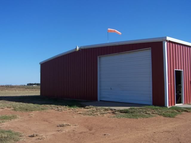
The door is up and it works!

George, hear are a few pics you asked about"

Image

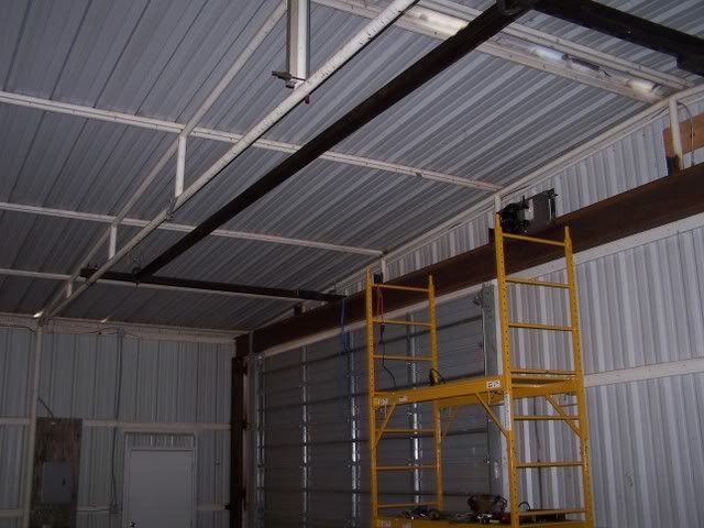
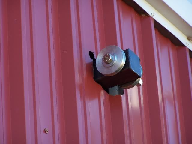
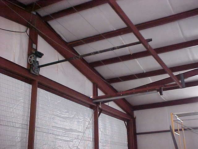
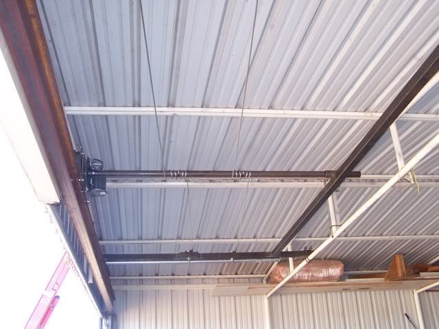
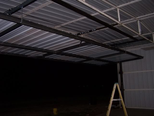
Here is the connection of the overhead frame to the truss.
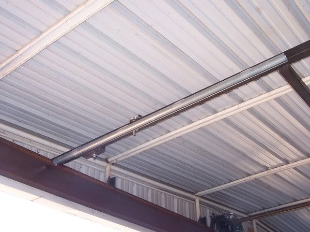
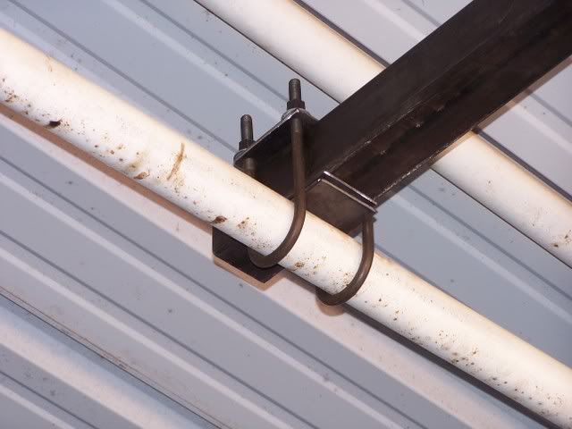
Image
Trolley track

Image
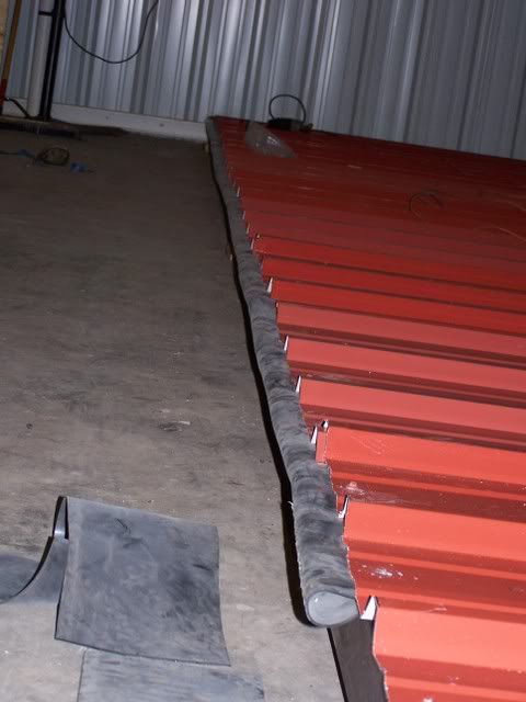
Installing lift cables

Image
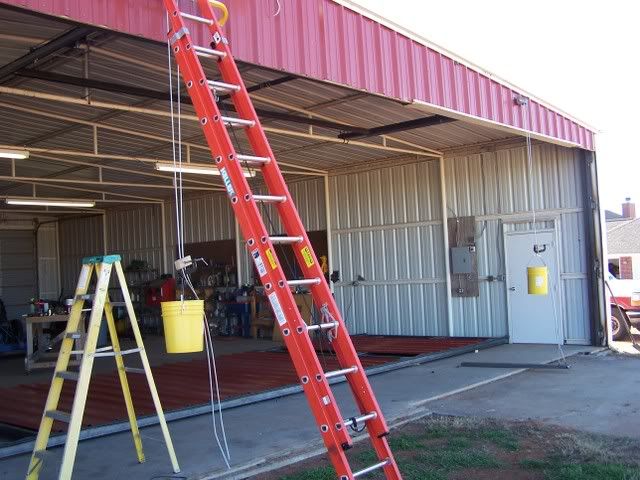
5 Gal buckets of gravel to keep cables snug

Image
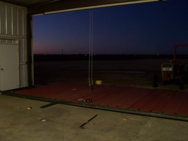
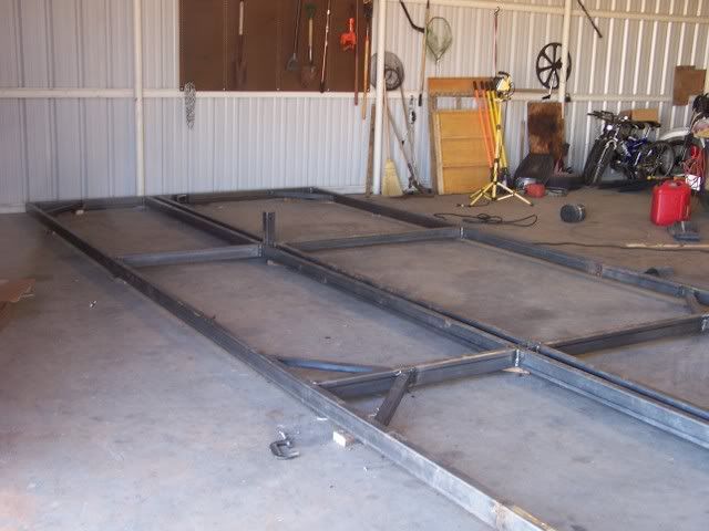
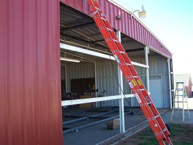
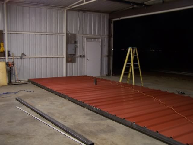
Getting ready to lift into place

Image
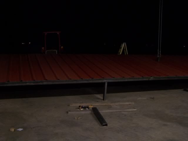
Lifted about 2 feet and checked that everything was happy.

Image
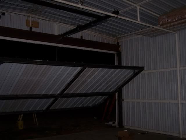
Side supports are in place and the door is being lowered into the "closed: position

Image
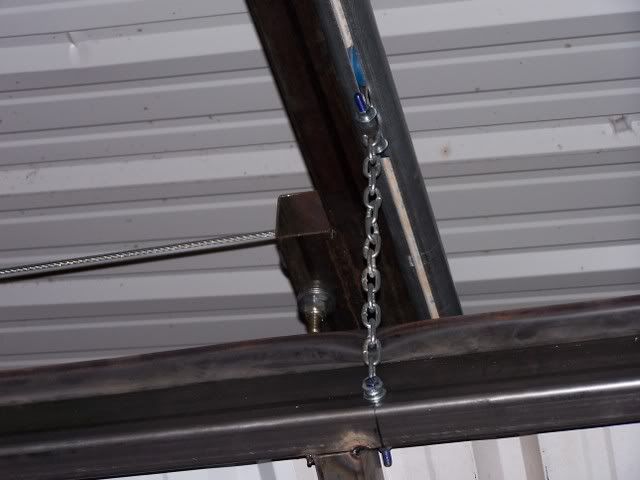
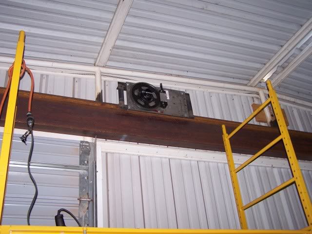
Trolley and chains are attached to the top of the door
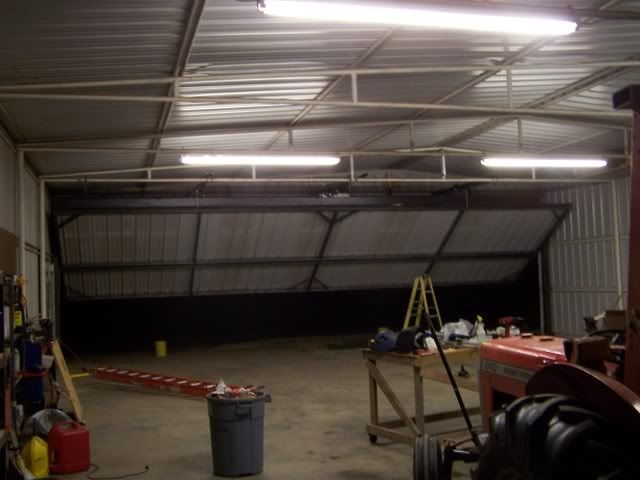
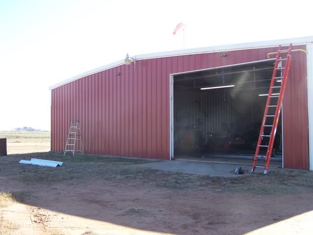
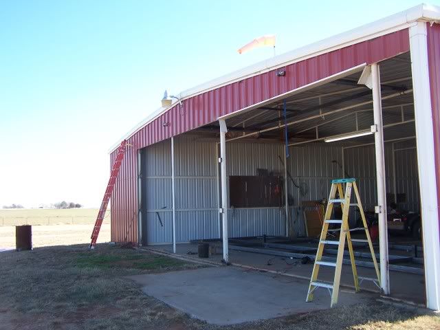
Image
First time!

Image
DONE!!!

:D :D :D :D

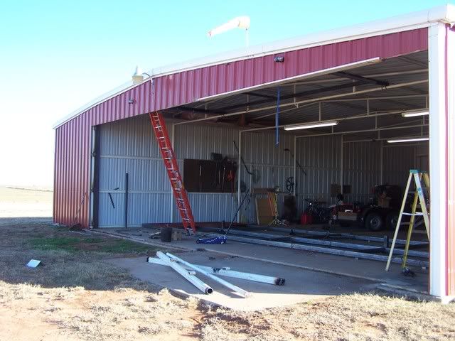
There is still a fair bit of work to do. The sheeting is only attached at the edges and needs to be finished. I still need to run the welds on the back of the door that was against the floor during assembly. I have to measure and buy trim and flashing to finish the outside of the opening.

I have to do a bit of tweaking as the wheels that guide the sides are free at the bottom of the travel but bind a bit at the top. I also will work on leveling the door at the full open position. A quick measure tonight showed 10'4" of clearance. That's about what I expected and is limited by he existing height of the barn.

The door is a bit lighter than Georges and it will not close all the way by gravity alone. I have to pull on the bottom half. The resistance is from the weather stripping but that may not be a bad thing.

I have and extra 6 feet of cable that was used to raise the door from the floor. I may need to remove the excess as the wraps are getting into each other on the pipe when the door approaches full open.

The only big disappointment so far is that I missed lining up the door sheeting ridges with the existing sheeting above the door. I thought I measured it correctly but missed by about 1.5 inches. Oh well.

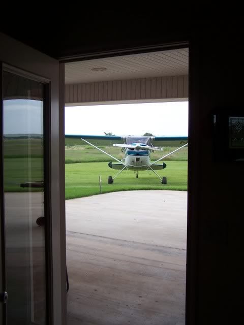
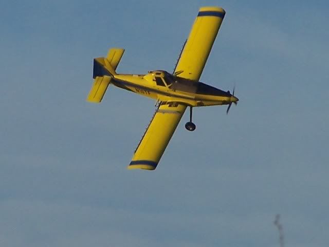
I hope to get the plane into the hangar tomorrow. I'll post that final pic soon. Cheers.

Bruce
Bruce Shipp
former owners of N49CP, '53 C170B
4-Shipp
Posts: 434
Joined: Mon Apr 22, 2002 11:31 pm

Post by 4-Shipp »

Image
By-the-way, ... that looks like about a 14" beam... is that right, Bruce? (Oughta be plenty-strong! Mine is a 10" beam for a much heavier door. Compare it to the rafter above it, which is 14".)

George, the header is a 12", 16# beam. Overkill, yes, but extra steel was cheaper than detailed engineering analysis to determine the minimum required. I actually found some nice web sights that had some plug-and-play calculators for determining deflection in I-beams under specific loading conditions. For a 40' beam loaded at 2 locations such as mine, the max deflection at the center was calculated at 0.904". This was for a beam anchored at one end and only supported at the other (free to move left and right as the beam deflects and returns. My beam is actually anchored at both ends and supported at 5 spots along the length by welding it to original truss, so my deflection would be significantly less. I have not figured a good way to measure the deflection under load as the door is in way and prevents me from measuring straight down to the floor. I'll figure out something.

Bruce
Bruce Shipp
former owners of N49CP, '53 C170B
User avatar
GAHorn
Posts: 21291
Joined: Fri Apr 12, 2002 8:45 pm

Post by GAHorn »

Anther way to influence closing action is to support it at slightly higher points at the ends. (But a simple shim placed on top of your support uprights may just do the trick. There's not much need for actual deflection of the weatherstrip. You can test it by placing a shim on top of the uprights at the ends so the wheel can rest on it slightly higher.)

When you say the cables are "getting into each other"... do you mean they actually try to wrap up onto each other? That's pretty difficult for me to imagine.... they should not be harmed by wrapping up alongside each other.

I'd be surprised if there were deflection of that header of any significance at all. My 10" header deflection is not measureable with a tape, (but that may be partially assisted due to the entire webbing above the door being constructed of I-beams/Flange-beams rather than pipe.) Your construction is clearly very strong, especially since you've got it so well supported at the ends. I'd stand beneath it!

Sure looks like a nice door, Bruce. Fun stuff, heh?

When's the fly-in/hangar-party? :P
'53 B-model N146YS SN:25713
50th Anniversary of Flight Model. Winner-Best Original 170B, 100th Anniversary of Flight Convention.
An originality nut (mostly) for the right reasons. ;)
Post Reply
Cessna® is a registered trademark of Textron Aviation, Inc. The International Cessna® 170 Association is an independent owners/operators association dedicated to C170 aircraft and early O-300-powered C172s. We are not affiliated with Cessna® or Textron Aviation, Inc. in any way.