170C wrote:George, share your photos with all of us.
…
OK, but this is before I finished completely and got the area picked up.
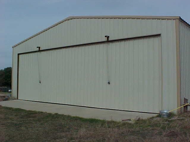
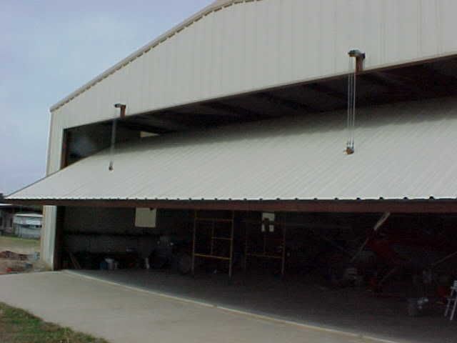
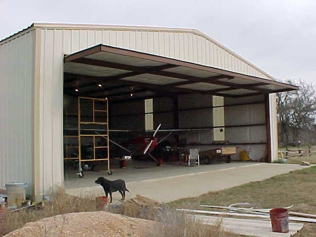
Outside View. Door measures 14' X 44'. The door is not actually resting on the concrete. It is suspended on two axles/steel-wheels at each end, mounted slightly above the midpoint of the door-ends. They are captive in a track built into the hangar-frame. (The hangar opening is framed by 10" flange beam (I-beam.) This means the door is free to pivot as it is lifted. The door structure is predominantly made of 2"X6" steel rectangular tubing. 3" square tubing protrudes thru the header of the bldg and has 3 sheaves (pulleys) on the outer end for the operating cables. That 3" sq. tube is about 9 ft long, most of it inside as you'll see, and it is resting on an 10" beam which makes the header across the top of the door opening. The 3" tubing provides a mounting surface for the 3 pairs of sheaves inside that take the cable from the spindle, and turn it outward so it can exit thru the header, over the outer 3 pairs/sheaves and down to the door's pickup points.
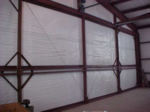
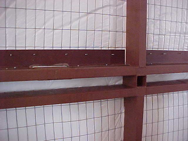
Inside View. The two "diamonds" are made of 2" angle and are used to surround and stiffen the inside area of the cable pickup points. Notice the pick-up points are between dual 2"X6" rect. tubing. These act like a wing-spar to prevent the door from bending or sagging when fully open. (Also, the door is 44' wide and is being picked up 11' in from each end, so each pickup point is actually a balanced 22' span. This door couldn't sag if it wanted to.)
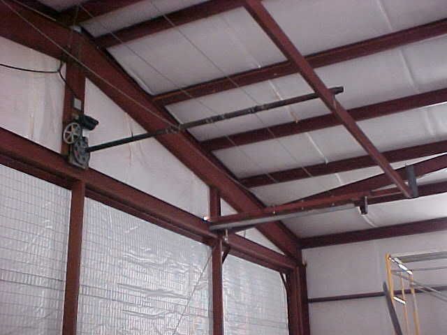
Boat Lift, Spindle (2" X 10' black-iron pipe), and supports for horizontal sheaves. A 1/2 hp electric motor spins a worm gear, which turns a ring-gear, thru which that spindle (2" pipe) is mounted. The spindle is thereby twisted, wrapping the cables about the pipe and thru a system of sheaves (pulleys) pull the door progressively upward and the top of the door inward. Since the (3) cables pass thru the spindle and are counter-wound around it, the stress of lifting the door is completely opposed by itself,...there is no strain at all on the pipe. The end of the pipe opposite the lift is actually free-floating within a light stanchion made of 2-1/4" pipe welded atop the 2X6 rect. tube. Smeared a little grease inside to prevent sqeaking sounds. The door goes up/down almost silently except for the whirring of that 1/2 hp electric motor. (Uses 12 amps.)
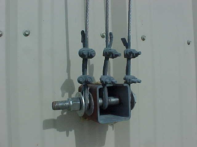
Cable attach points outside view. This point is about 14 inches below the center of the door to provide for tipping the top inwards into the hangar prior to any actual lifting of the door. This is made up of 3" sq. tubing and a grade 5 bolt, etc. The cut ends of the cable were sealed with JB Weld (epoxy) to preclude fraying, then all the hardware was sprayed with cold-galvanize zinc-rich paint to prevent rusting. The opening thru which this 3" tubing passes was then sealed with 50-year RTV to prevent water from getting thru to the insulation, especially when the door was up/open. The inside end of the 3" sq. tubing was closed off by welding a flat plate across it, tying the two spars together also. (Didn't want to give mud daubers a free ride into the hangar with an open 3" tunnel.)
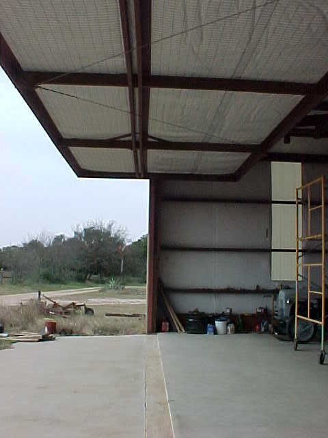
Inside view closeup of "spar" at the center of the door. This piece of 3" sq. tube does not penetrate thru the door, but is only used as a spacer for the spar. (That's why I didn't need to weld a plate across it or close it off....no daubers can get thru here!)
Cables exit and go over sheaves down to outside attach point. (These are actually grade 8 bolts because I already had them in stock. Grade 5 would be fine. I lubricate the bolts/sheaves once a year with waterproof boat-trailer wheel bearing grease. 4 years and several hundred operations show negligible wear. I got bored one day and drilled all the sheave-bolts lengthwise from the head down the centers and then crosswise where the sheaves ride, and tapped/installed a grease-zerk-fitting in the bolt-head so I could just shoot a dab of grease in there and not have to disassemble. Not necessary, but I was bored and having fun. This is really a low-stess useage.) That lower/vertical piece of 3" tubing was later cut off (it was originally intended for additional closing mechanism which proved unnecessary) and a sheet-metal rainproof box or bird-house was constructed from matching R-panel to protect this entire sheave and cable assembly from rain. If I can remember to take a pic of it, I'll post it also.

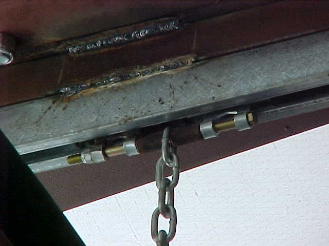
The door begins to open...first the top tips into the hangar, and then as the cables continue to wrap around the spindle, the top of the door is supported by chains and trolley-tracks, preventing it from falling into the hangar. Look very carefully at the top of the door just above the third upright-frame from you and you'll see the chain which is welded to the top frame of the door and the other end attached to the track-trolleys.
Here's a close-up of the track trolleys. Note that the top of the door is supported by two captive track-trolley systems, one above each main cable pickup point. The top of the door is suspended by those flexible chains. Designed for lightweight hanging/slider barn doors, I bought them at Tractor Supply. I used two tracks, and four trolleys (two trolleys are connected by a 3/8" X 8" bolt which passes thru the chain.):
The door continues to open. The cables are lifting it from the pickup points at the spar, and the top of the door is being supported by the chains/trolley-tracks. (The boat lift/door can actually be stopped at any place along it's travel and it will remain in that position. No brake is required due to the worm/ring gear arrangement of the boat-lift.)
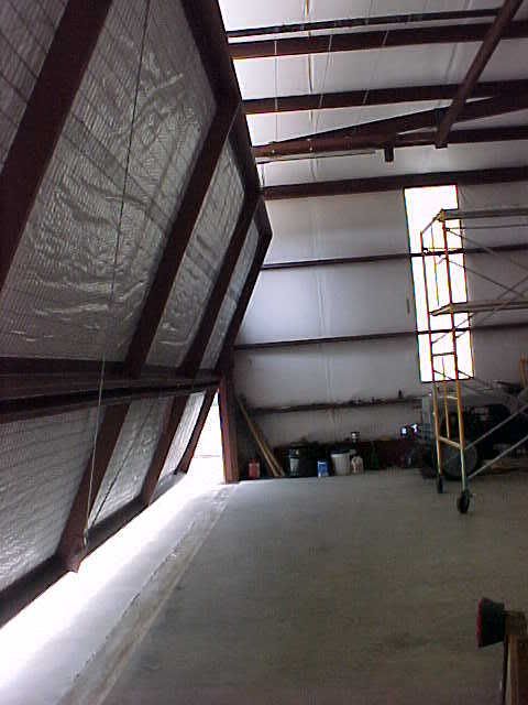
Fully open it steals only 8 inches of headroom and is absolutely unaffected by wind in any position, either fully or partially open because the ends of the door is secured within a track made up of two 6" steel wheels captured within I-beam and angle. The wheels are mounted 8" above the center ends, so the door at rest is bottom heavy and remains closed naturally, even against strong winds. When the door is fully closed, it is resting on those wheels in the lowest part of the end-tracks...the door is not actually resting on the slab. That's why it pivots open so easily when lifted by the calbes, clearing the door header before any portion of the door raises.
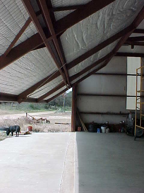
Since the door is 14' tall, and is pivoting horizontally as it is lifted, only 7' of cable needs to be wound up on the spindle to bring the door fully open. 2" pipe has an outer diameter of slightly more than 6", so only 14 turns of the pipe will fully open the door. (The door only needs to move up 7' to be fully open.) From fully closed to fully open takes less than 3 minutes. It could be speeded up by using 2-1/2" pipe for a spindle with no problem but I'm OK with the speed as it is. (Gives me time to kick the chocks, pull the covers, etc.) Fully open, about 8' of door is overhead inside the hangar and 6' outside, providing a short awning effect. (Kinda fun to sit out in the hangar when it's raining and drink a beer. All the water hits the apron outside the doorway.)
The major matl's used were:
3" square tubing (3/16" wall) one 25' stick
2" X 6" rectangular tubing (11 ga.) 6 (six) 40' sticks.
12 5" steel sheaves
160' 7X19 stainless aircraft cable(7,000 lb rated), thimbles, clamps.
5/8" grade 5 bolts for sheaves (six were 5" long, four were 8" long)
Ny-Lok Nuts and large flat washers
Fiberglass insulation (one roll, 6' X 150')
2"X4" grid, goat-wire fencing, 60" wide X 150' long to support insulation. (3 rolls)
8" X 11 lb flange-beam for header support and end tracks. (2 X 25')
2" square tubing to suspend roller tracks from 3" sq. tubing sheave supports. (1 X 20')
Two 6" steel wheels and 3/4"X 8" grade 8 bolts/nuts for door end-support at rest and to capture door ends within vertical track made up of left-over 8" flange beam and left-over 4" angle.
Track and trolleys for upper door support and chain, 3/8"X 8" bolts. (20' of track)
4"X4" angle for general support and to suspend 3" sq. tubing from beams. (one 20' stick)
115 volt boat lift rated single-pull at 4800 lbs. (door weighs 1700 approx)
2" pipe, 10 ft long for spindle, and pipe stanchion to capture end opposite boat lift. (The boat lift supplier can help with all hdw related to the lift.)
14 ga. "R" panel in 3' widths, 14' high (15 panels)
2"X4" base-angle to provide for attaching the R-panel to the rect. tubing. (5 sticks, 20' long)
Neoprene washer metalscrews for R-panel and base-angle.
2"X2"X36" angle for stiffeners at corners and cable pickups. Probably completely unnecessary after sheet metal is installed. It was probably overkill. (16 each)
3/8" galv. cable for strain relief of lower center of door to prevent anticipated sagging (The apron of the hangar was not exactly poured level and was about 1/2" higher in the center than at the ends. The cable was anticipated necessary in order to guarantee the door would not drag on the apron on opening/closing...proved unnecessary, especially after the sheet metal was installed. More overkill.)
Weather seals are made of black EPDM 14" wide and the appropriate length (either 44' for top/bottom, or 14' for ends of door), folded in half so it formed a loop, and stapled to itself. It was then slipped beneath the R-panel/J-trim before the panels were screwed completly down. Since the door is surrounded top/ends by 8" flange beam and bottom by the slab, about 2" of the folded weatherseal was left exposed to completely close the door opening against weather and insects. (I hate mud daubers.)
J-shaped trim to finish the edges. (5 sticks X 20')
A sheetmetal screwgun for the R-panel and goatfencing.
With three cables counterwound acting like six cables, the safety factor is quite high, about 42,000 lbs of capability lifting a 2400 lb door. The lift lightly loaded, and the trolleytracks are rated at 600 lbs each, and with two sets of trolleys each giving 1200 lbs of capability. But the balance of the door fully open only places 120 lbs on them.
Probably used about 50 lbs of 7018 welding rod. (6011 or 6013 would probably be OK also, but I had the 7018 low hydrogen (for strength) left-over from building the hangar. The matl's had sat around for two years and was slightly rusty so I used a stick welder on it for penetration. I had two helpers (a cousin who is a professional welder and a goofy guy from Toledo Bend who is a professional goofy) help with most of the heavy construction. A scaffold and a welding machine, mitre/chop saw, and an angle grinder for most of the work. After the framework was all up, I used an angle-grinder with a wire wheel to brush it all off before painting it with Ospho (phosphoric acid) to rust-proof it, then painted it with red-oxide oil-base paint.
Then goofy and George Courtney (NH area rep) came down for Xmas and helped me put on the insulation and screw on the sheet metal in one day. Total time spent actually working was about 10 days.
The black lab is my Roulette! The edge of the concrete is her boundary unless I release her with her secret word. She's a really sweet dog with a desire to please. A real frisbee expert.
